
StreamLink Overview
StreamLink transports live signals between on-site encoders / studios / cloud processing systems. This document first looks at the console menus and then configures the transport path in the order Event → Flow → Input → Output. Transcoding by resolution is performed in StreamLive, and viewer-facing HLS distribution is configured in StreamPackage and CDN.
Console Menu Map
| Menu / Screen | Role | Task performed here |
|---|---|---|
| Event list of Flow | Bundle of transport paths per event / service | Create event, select an Event, enter Flow management |
| Flow management | Manages the individual transport paths that belong to an Event | Create a Flow, connect Input / Output, start / stop individually |
| Security Group | Manages the IPs allowed to access inputs / outputs | Register the public IP ranges of the sender or the receiver |
| Usage statistics | Query usage | Check transport usage by query period and target |
| Gateway | Manages the Gateway configuration | Configure in transport designs that use Gateway |
An Event is a management bundle, and a Flow is a transport path. Once you create an Input and an Output, you can check the sending / receiving connection points.
1. Creating and Selecting an Event
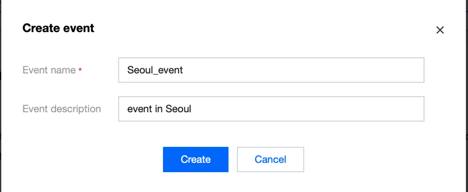
In the StreamLink console, select Create event. Enter an event or service identifier as the name and the purpose as the description. For example, you can use demo_event and Encoder to processing service.
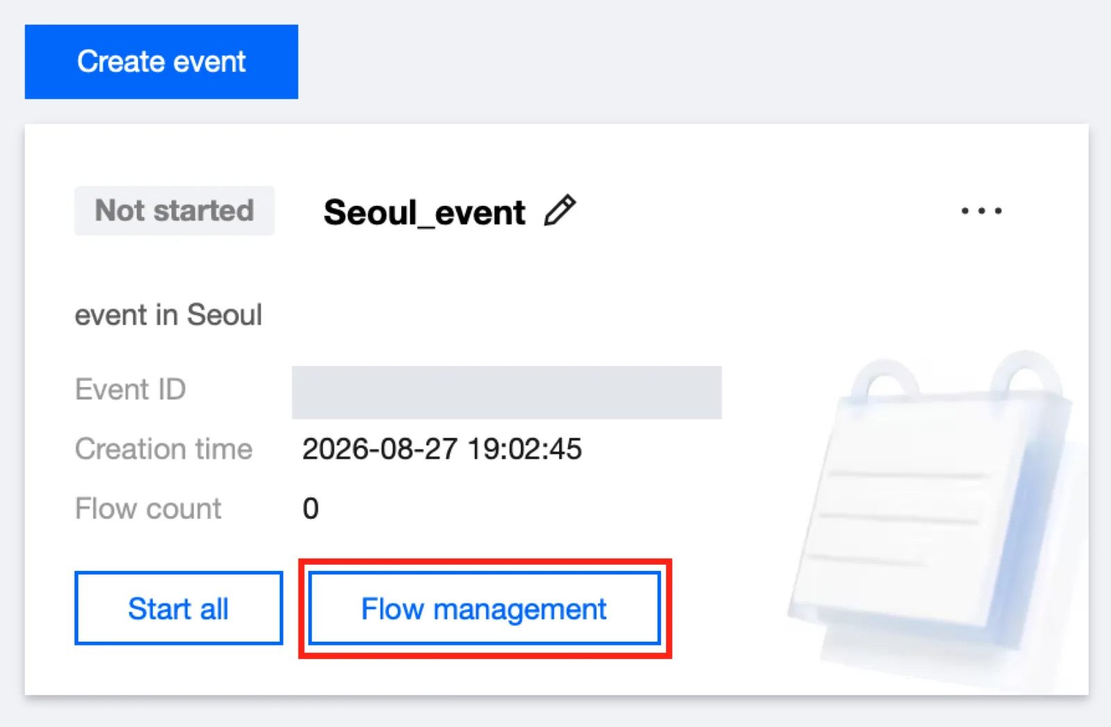
Select Flow management of the saved Event. Start all affects the multiple Flows inside the Event, so at first use the start button of each individual Flow.
The names / regions / input values in the captures are examples for describing the screens. Specify them to match the transport path you use.
2. Creating a Flow
In Flow management, select Create and create a transport path.
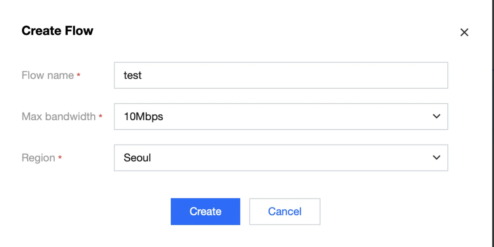
| Field | How to set | Notes |
|---|---|---|
| Flow name | A path-identifying name such as demo_flow | Distinguish primary / backup paths by name |
| Max bandwidth | A value that accommodates the source bitrate and transport headroom | Consider audio / overhead and fluctuation as well as video |
| Region | The region where the input path is configured | Consider the location of the sending equipment and the network path |
MaxBandwidth in API is in bps. After creation, check the status and the Flow name, then add an Input.
3. Supported Input Protocols and Selection Criteria
The table below is based on the input types in the official console guide. Additional types may be displayed depending on account / service updates, so check the supported scope of the actual console and of the API version together.
| Input protocol | How the source comes in | Mainly used situation |
|---|---|---|
| SRT Listener | The sending equipment connects to StreamLink as a Caller | Receiving SRT Push from an external encoder |
| SRT Caller | StreamLink connects to the source Listener | Pulling from an SRT source that is waiting for connections |
| RTMP_PUSH | The encoder sends to the generated input address | Connecting RTMP sending software / equipment |
| RTMP_PULL | StreamLink connects to the source RTMP address | Pulling from an external RTMP source |
| RTP | The sending side transmits to the generated input address | Connecting RTP-based equipment |
| RTSP_PULL | StreamLink connects to the source RTSP address | Integrating an RTSP source |
| RIST Listener | Receives the connection from the source Caller | Connecting sending equipment that supports RIST |
The Caller/Listener role in SRT determines who starts the connection. Input / output is the data direction, while Caller / Listener is the connection establishment role.
4. Adding an Input
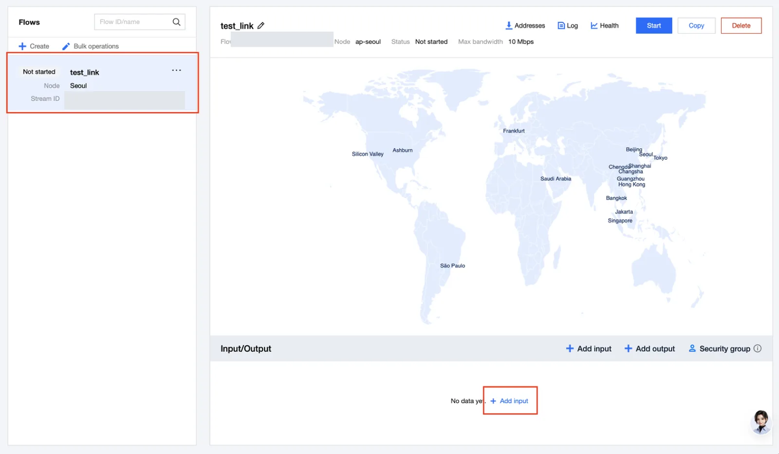
Select a Flow and open Add input. Select the name, protocol, and input region / availability zone, then configure the fields of that protocol.
| Selected method | Values to prepare |
|---|---|
| Push or Listener | The actual public IP used for sending, the allow policy, and the required encryption settings |
| Pull or Caller | Source address / port, the required Stream Key or Stream ID, and source credentials |
| SRT | Connection role, latency buffer, encryption key and key length |
| Failover-supported input | Primary / backup transmissions to send to the two generated addresses, and a switchover verification plan |
The IP allowlist is an access restriction, and encryption protects the transported content. After saving the input, check the address required for sending in Addresses.
5. Output Protocols and Connection Direction
First check the supported combinations of input and output.
| Input type | Output types in the official console guide |
|---|---|
| RTMP_PUSH / RTMP_PULL | RTMP_PUSH, RTMP_PULL, SRT |
| SRT | SRT, RTMP_PUSH, RTMP_PULL |
| RTP | RTP |
| RTSP_PULL | RTSP_PULL |
| RIST | RIST |
| Output method | Side that starts the connection | Destination to configure |
|---|---|---|
| RTMP_PUSH | StreamLink | The URL and Stream Key of the receiving platform |
| RTMP_PULL | The receiving system | Enter the address generated by StreamLink into the receiving system |
| SRT Caller | StreamLink | The address / port / Stream ID of the peer Listener |
| SRT Listener | The Caller of the receiving system | The output address generated by StreamLink |
When connecting to the RTMP_PUSH input of StreamLive, use the RTMP_PUSH output of StreamLink. The StreamLink Input address for sending and the destination StreamLive Input address are different addresses.
6. Adding an Output and the Number of Concurrent Connections
In Add output, specify the output type, name, region / availability zone, protocol, and destination.
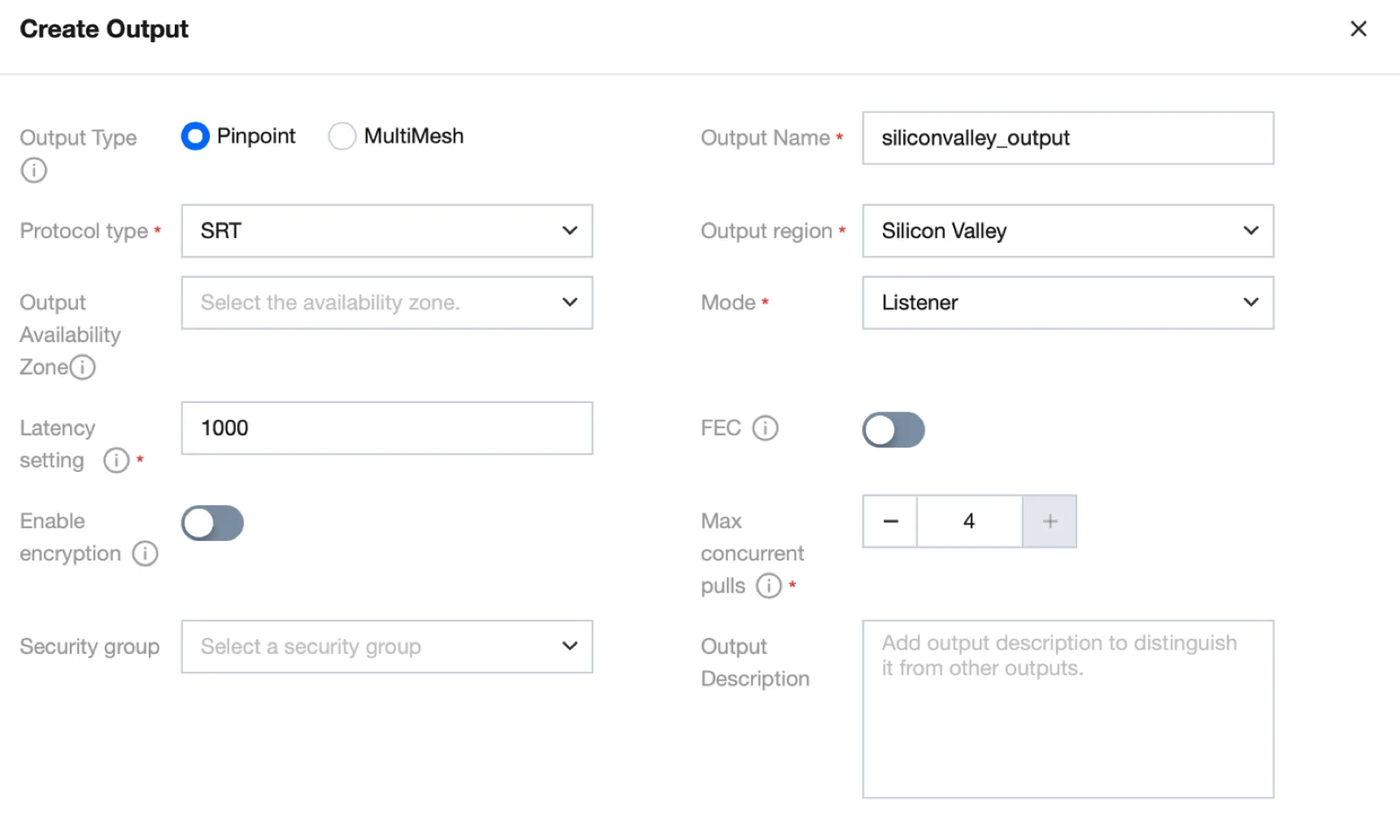
| Output type | Purpose and limits |
|---|---|
| Pinpoint | 1 Push or a maximum of 4 Pull per output. The per-protocol connection count applies |
| MultiMesh | An SRT Listener output Pulled by many receivers. The official documentation states that there is no limit on the number of Pulls, but access control and usage management are required |
Pinpoint RIST Listener supports 1 concurrent Pulls according to the official documentation. As the number of output nodes and connections increases, the cost changes as well.
7. Start / Log / Status Check
After selecting Start for the Flow, begin sending the source and receiving at the destination. The destination server or receiver must be ready.
| Screen | What to check |
|---|---|
| Addresses | Input / output addresses, node IP, port, protocol |
| Log | Connection / termination / reconnection and response records |
| Health | Input / output bitrate, per-protocol loss / retransmission metrics |
| Receiving system | Actual video / audio, stalling and latency |
Check the input signal, output transmission, and playback in the receiving system separately.
Detailed Procedures by Feature
- Event and Flow basic settings
- SRT Input / Output Configuration
- RTMP Input / Output Configuration
- Flow Start / Stop
- Check Address / Log / Health
- Change Input / Output
- Primary / Backup Redundancy and Switchover Verification
- API / CLI
Ending and Official Documentation
After the test ends, clean up the Flow and its dedicated resources. For Event-level tasks, check the list of included Flows before proceeding.