
Configuring an SRT Flow
Video from the SRT source device is received by StreamLink and delivered to the receiving system. In this example, both the StreamLink input and output are set to Listener. The source device and the receiving system each connect as Caller.
Connection Roles
| Segment | StreamLink role | Peer device role | Video travel direction |
|---|---|---|---|
| Input | SRT Listener | SRT Caller of the source device | Source device → StreamLink |
| Output | SRT Listener | SRT Caller of the receiving system | StreamLink → receiving system |
The Caller is the side that initiates the connection. In this example, the receiving system connects as the Caller and then receives the video.
Preparation Before Starting
- Complete the Event configuration.
- Confirm that the source device and the receiving system support SRT.
- Check the public IPs of both devices, whether UDP communication is allowed, and the bitrate.
- If you use encryption, you must be able to set the same key and key length on both ends.
1. Creating a Flow
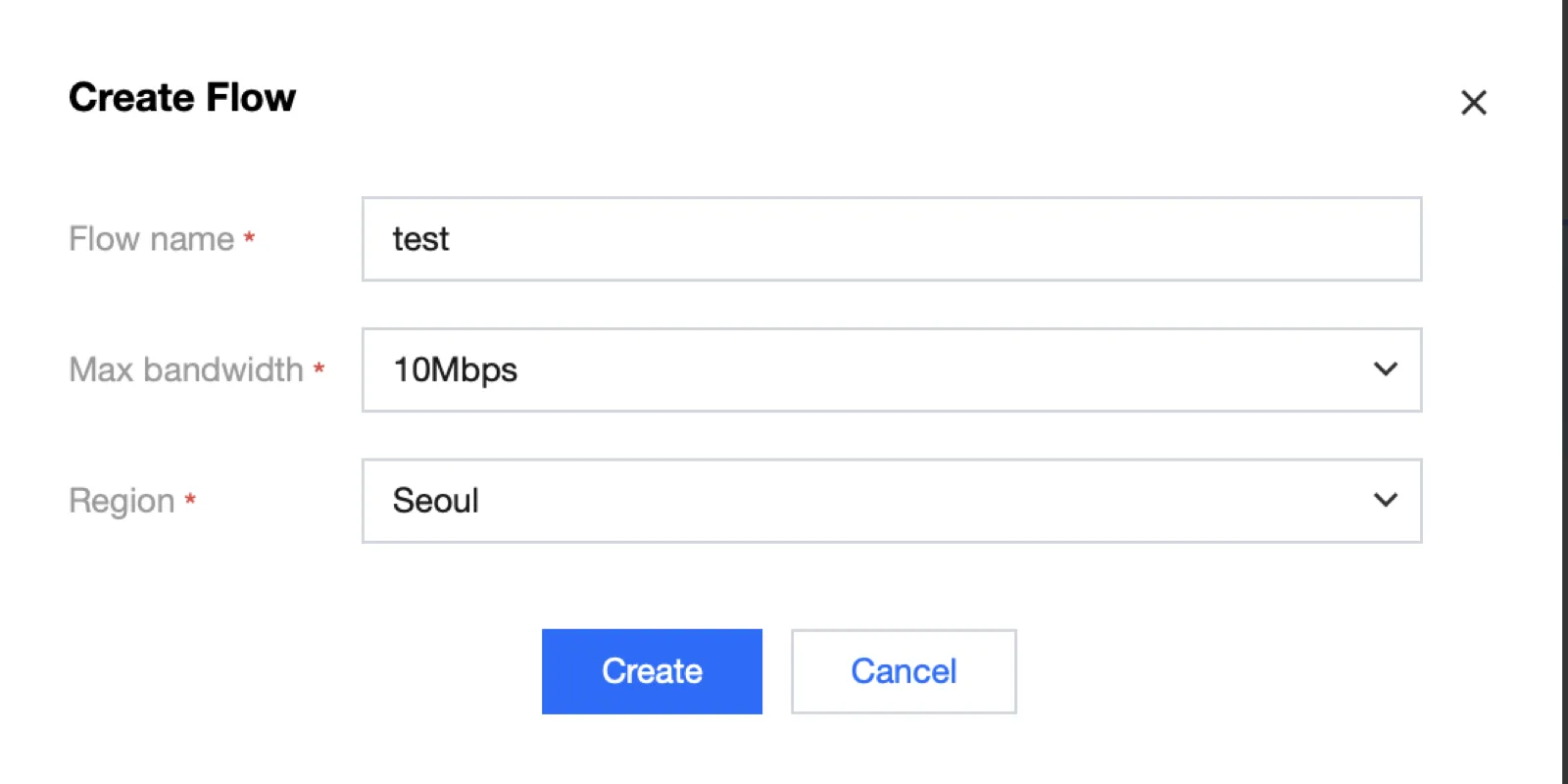
In Flow management of the Event, create a new Flow. Set the name to demo_srt, and set the bandwidth limit to a value that can accommodate the source and the transmission overhead.
2. Adding an SRT Input
Select the Flow and open Add Input.
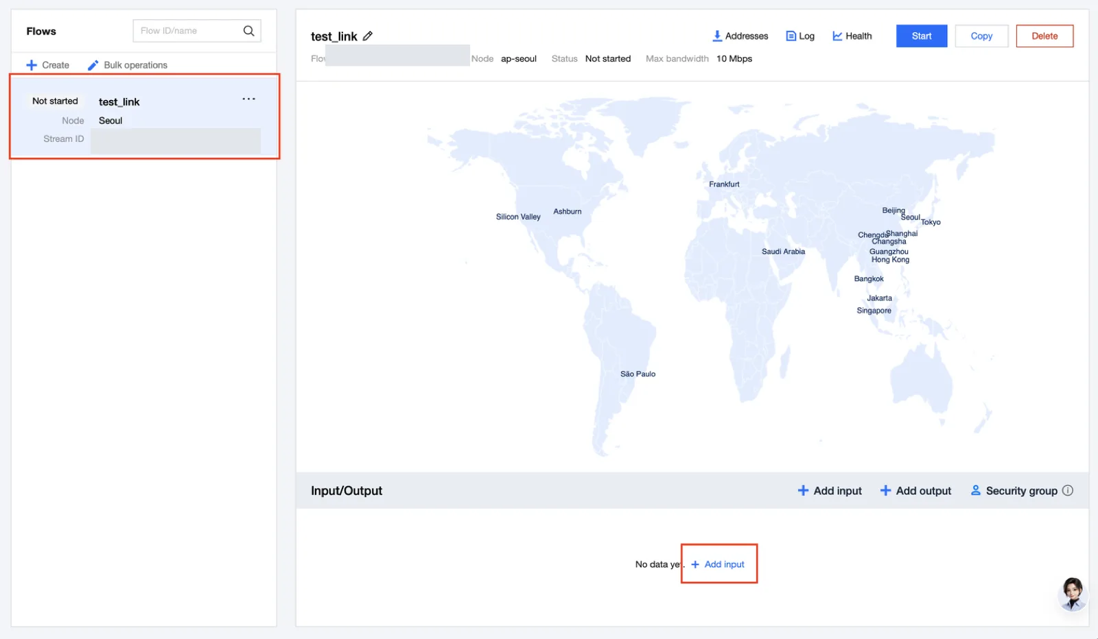
Select the input name / region / availability zone, set Protocol to SRT, and set Mode to Listener.
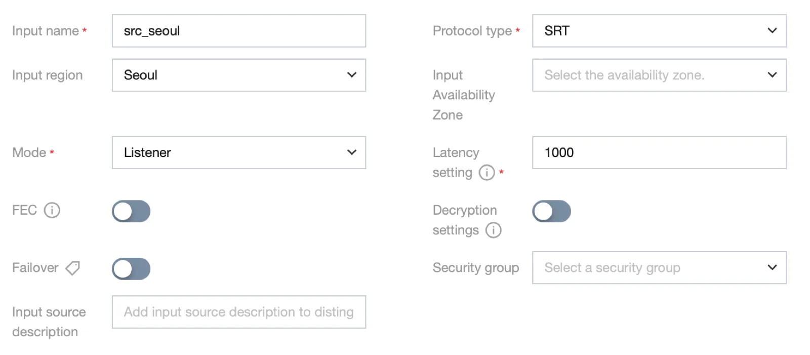
| Setting | What to enter |
|---|---|
| Input name | A distinguishable name such as demo_source |
| Region / Availability Zone | Location of the input node that will connect to the source device |
| Mode | Listener |
| Latency | A value that accounts for the RTT / jitter / loss of the source device ↔ input node segment |
| Security group / IP allowlist | The actual public IP range of the source device |
| Decryption | When encryption is used, the same key and key length as the sending side |
The IP allowlist restricts the peers that can connect. Encryption protects the transmitted content.
After saving, check the input address in the Address list and apply it to the source device. Use the values from the console for the address / port / required Stream ID.
3. Adding an SRT Output
In Add Output, select the Pinpoint type used for basic one-to-one delivery and configure the SRT Listener output.
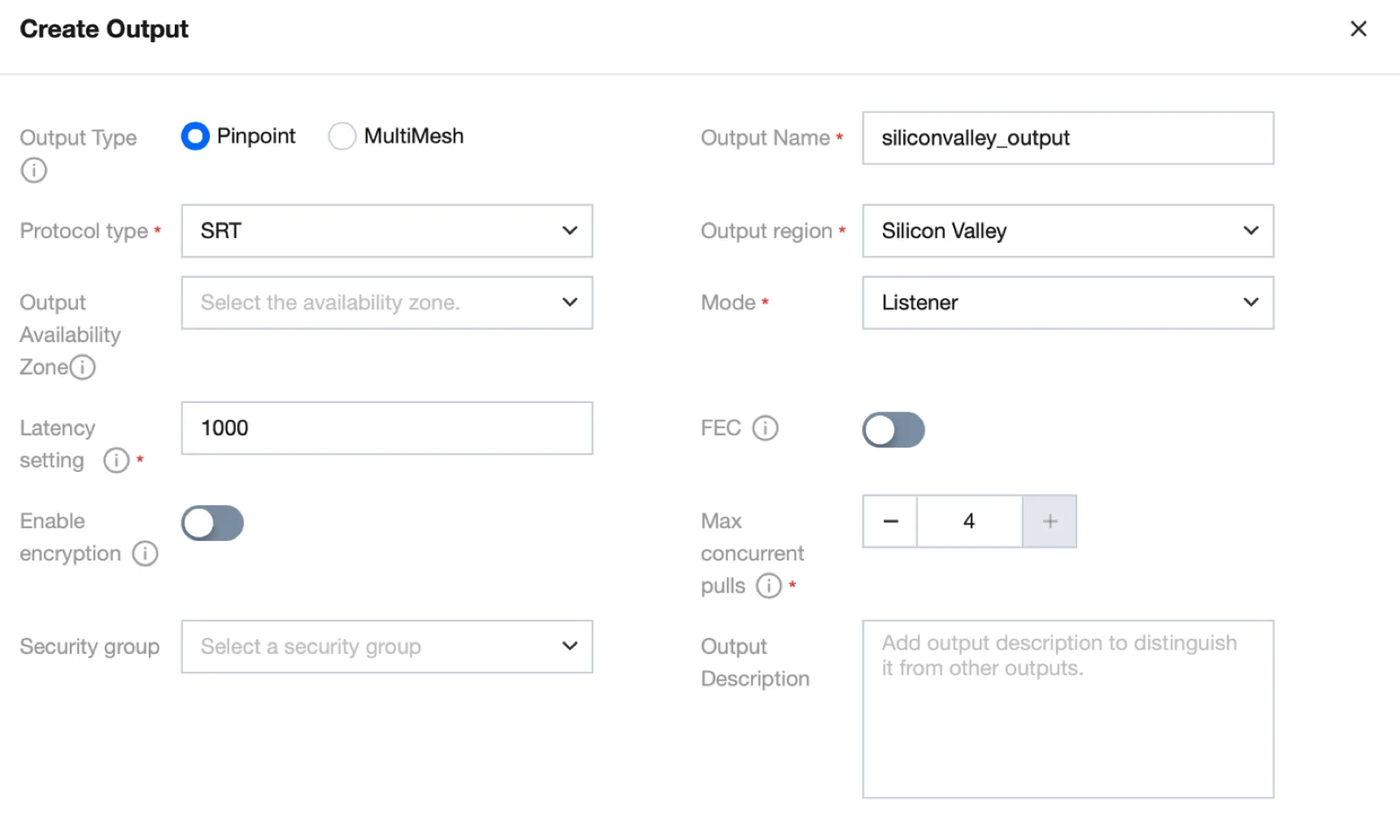
| Setting | What to enter |
|---|---|
| Output name | demo_receiver |
| Region / Availability Zone | Location of the output node that will connect to the receiving system |
| Mode | Listener |
| Latency | A value matched to the conditions of the output node ↔ receiving system segment |
| Max concurrent pulls | The number of simultaneous receiving connections needed. A Pinpoint SRT Listener allows a maximum of 4 |
| Security group / IP allowlist | The public IP range of the receiving system |
| Encryption | When used, apply the same key and key length on the receiving side |
Enter the generated output address in the receiving system and select SRT Caller mode. If the configuration requires the receiving system to be the Listener, you must change the StreamLink output to Caller and specify the receiving side address as the destination.
Latency Setting Guidelines
The initial reference values in the official documentation are 120ms if the peer device and the corresponding StreamLink node are in the same country, 200ms if in different countries, and 1,000ms if on different continents. In an actual environment, adjust them based on the RTT, jitter, and the time required for retransmission.
For the Seoul input segment, set Latency based on the RTT between the source device and the input node. Adjust the input / output connections according to their respective network conditions.
4. Start and Verification
- Start the Flow.
- Send video from the source device to the input address.
- Connect to the output address from the receiving system.
- Check the input / output bitrate and connection status in the console.
- Check the received video and audio, stuttering, and delay, and also review the loss / retransmission / drop metrics.
If the connection fails, first compare the Caller/Listener combination, UDP communication, allowed IP, address / port, and encryption settings. If the connection is established but the video is corrupted, check the source bitrate and the loss recovery status.
Redundancy and Cleanup
After confirming basic playback, add the redundancy configuration. After the test ends, stop the Flow.